Quick answer: A combustion control system does three jobs — hold the air-to-fuel ratio as firing rate changes, enforce the safety interlocks that prevent unburnt fuel from accumulating, and expose the diagnostics that let an operator distinguish a process problem from a burner fault. The electric control cabinet is where those three functions are implemented, which is why it should be specified as part of the thermal system rather than purchased separately afterwards. The most common commissioning failures are not burner faults at all: they are ratio curves set without measuring flue gas, interlocks bypassed to get a line running, and no baseline recorded for future comparison.
What a combustion control system is actually for
Combustion control is often described as "keeping the flame lit" or "regulating temperature". Both descriptions understate what is involved and miss the safety function entirely. A control system for an industrial burner performs three distinct jobs, and each has its own failure mode.
Job one: mixture control across the firing range
Combustion requires fuel and air in the correct proportion. The proportion is not constant: as firing rate falls, the air and fuel flows must fall together along a defined curve, and any deviation produces either unburnt fuel (rich) or wasted heat carried out of the stack (lean). The control system's first job is to hold that relationship across the entire modulating range — not only at full fire, where a burner looks good on almost any setting.
Job two: safety interlocks
The second job is less visible because it does its work only in the moments before and after ignition. It prevents the burner from attempting to light when fuel may have accumulated in the chamber, and it shuts the fuel off within a defined time if the flame is not proven. This is the function that regulators examine and that insurance inspectors ask about; it is also the one most often compromised during a rushed start-up.
Job three: making faults diagnosable
The third job is frequently treated as optional and is not. A control system that reports only "burner fault" leaves the operator unable to distinguish between a genuine burner problem, an air supply problem, a fuel pressure problem and a process problem. The cost is downtime measured in hours rather than minutes, and it is a design property of the cabinet, not something that can be added later.
Ratio control: holding the right mixture across the firing range
Ratio control means maintaining a defined relationship between fuel flow and combustion air flow as the burner modulates. The relationship is expressed as a curve, and the curve has to be established for the specific burner, fuel and chamber — it cannot be copied from another installation.
Excess air, and why the set point changes with load
Perfect stoichiometric combustion uses exactly the air needed to burn the fuel. In practice a margin of extra air, called excess air, ensures complete combustion — but the correct margin is not the same at all firing rates.
At high fire, mixing is vigorous and combustion completes with modest excess air. At low fire, fuel and air velocities fall, mixing weakens, and more excess air is needed to avoid incomplete combustion. A ratio curve set as a straight line will therefore run too rich at low fire or too lean at high fire. The correct curve bends: relatively more air at the bottom of the range than the top.
This is why commissioning cannot be done at one point. The curve must be established at several firing rates, and the flue gas measured at each.
| Firing rate | Typical combustion character | What to measure |
|---|---|---|
| High fire | Strong mixing; can run close to stoichiometric | Oxygen and carbon monoxide in flue gas; stack temperature |
| Mid fire | Intermediate; the setting that determines most operating hours | Oxygen and CO; confirm the curve passes through smoothly |
| Low fire | Weak mixing; needs the widest excess air margin | Oxygen and CO; confirm flame stability, not just emissions |
The critical point is the last row of the last column. A burner can produce acceptable flue gas readings while sitting on the edge of flame instability. Stability must be confirmed by observation and by holding the burner at low fire for a sustained period, not by a single reading.
Mechanical, electronic and hybrid ratio control
Three approaches are used, with different implications for maintenance and repeatability:
Mechanical linkage. A cam and linkage assembly ties the fuel valve position to the air damper position. It is simple and needs no power to hold its relationship. Its weakness is wear: linkages develop play, and a small change in the linkage becomes a mixture error. It also does not compensate for changes in fuel calorific value or air density.
Electronic, parallel positioning. Separate actuators drive the fuel valve and air damper, each following its own position curve held in the controller. The relationship is defined in software, so it can be shaped and corrected without mechanical adjustment, and it can be re-verified by reading the curve rather than measuring the linkage.
Closed-loop, with flue gas feedback. A sensor measures oxygen in the flue gas and the controller trims the air flow to hold the target. This compensates for fuel composition changes, air density variation and mechanical drift. It costs more and adds a sensor that must itself be maintained, but it is the arrangement that keeps performance stable over years rather than weeks.
Safety interlocks and the pre-purge sequence
The safety sequence exists to answer one question: is it safe to introduce fuel? It answers in a fixed order, and each step must complete within a defined time.
The sequence and its logic
- Permissive check. Confirm all conditions allow a start: air flow available, fuel pressure in range, limits and interlocks healthy, no flame failure latched.
- Pre-purge. Run combustion air through the chamber for a defined period to displace any combustible atmosphere. The purge time is calculated from chamber volume and air flow, and it must be completed before any fuel valve opens.
- Ignition. Establish the ignition source, then open the pilot or main fuel valve. The order matters: the ignition source must be present before fuel, never the reverse.
- Flame proving. Confirm the flame within the trial-for-ignition time. If the flame is not proven in that window, shut the fuel off immediately and lock out.
- Run and modulate. Release the burner to the control loop once the flame is stable.
- Post-purge on shutdown. Run air after the fuel valve closes to clear residual combustible gases.
Where interlocks get compromised in practice
Three compromises appear repeatedly, and all three originate in the pressure to get a line running:
- Shortened pre-purge. A purge time reduced to save cycle time leaves combustible gases in the chamber. The correct purge time is a calculated value, and it should be recorded in the commissioning documentation so that a later change is traceable.
- Bypassed or defeated flame detection. Where a flame sensor faults intermittently, the temptation is to defeat it rather than replace it. This removes the primary protection against fuel accumulation after a failed light-off.
- Widened tolerances on pressure switches. Adjusting a switch so it no longer trips removes an interlock while leaving the appearance of compliance.
Each of these is a documentation question as much as a technical one. If the commissioning record captures the as-set values, any later deviation is visible; without the record, the deviation is invisible until an incident forces an investigation.
What belongs in the control cabinet
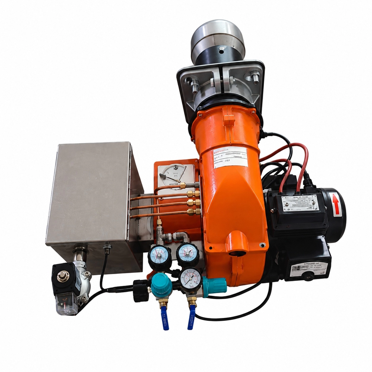
The supporting electric control cabinet is not a generic enclosure with a contactor inside. Its contents follow from the three jobs above.
| Function | Typical components | Why it matters operationally |
|---|---|---|
| Programmed start and safety sequencing | Burner management controller | Holds the interlock logic; the component that regulators assess |
| Flame supervision | Flame sensor and amplifier | Provides the signal that proves combustion and triggers lockout |
| Ratio control | Actuators, position feedback, or oxygen trim | Holds the mixture curve across the firing range |
| Temperature or process control | Controller with process sensor input | Converts process demand into a firing rate command |
| Motor and fan control | Contactors, overloads, variable-speed drive if used | Controls combustion air supply and its response to demand |
| Operator interface | Display, indicators, alarm annunciation | Determines how quickly a fault can be diagnosed |
| Power distribution and protection | Isolator, breakers, terminals | Allows safe isolation for maintenance and testing |
| Remote signalling | Dry contacts, or communications interface | Connects burner status to plant monitoring where required |
Two specification choices have outsized operational effect. The first is the operator interface: a cabinet that annunciates specific faults rather than a single general alarm repays its cost in the first significant downtime. The second is the spare capacity for remote signalling. Where a plant may later connect burner status to a monitoring system, providing the interface at build time is far cheaper than retrofitting it into a commissioned cabinet.
Environmental and electrical considerations
Control cabinets near combustion equipment face elevated ambient temperature, vibration and airborne contamination. These are installation conditions that affect reliability:
- Ambient temperature. Controllers, drives and transformers have maximum ambient ratings. Enclosure cooling — filtered ventilation or a cooling unit — should be specified from the measured ambient at the mounting location, not assumed from the factory ambient.
- Ingress protection. Dust and moisture in a boiler house or drying line are the normal case, so an appropriate enclosure rating and gasketing are required rather than optional.
- Cable routing. Flame sensor cables carry a very low-level signal and must be routed away from power and drive cables to avoid induced interference producing false flame indications.
- Earthing and screening. Proper bonding and screening protect both the flame detection signal and any communications link.
Commissioning procedure that produces a usable baseline
Commissioning is where the control system's performance is actually determined. A procedure that merely demonstrates the burner lights and reaches temperature leaves the installation functionally unverified.
Steps that should not be omitted
- Verify the gas train and fuel supply against the specified pressures and flow before first ignition — including all safety shut-off valves and pressure switches.
- Confirm the purge time is the calculated value, and record it.
- Establish the ignition point and confirm reliable light-off at low fire, repeated several times, since intermittent light-off is a common latent fault.
- Set the ratio curve at a minimum of three firing rates — low, mid and high fire — measuring oxygen and carbon monoxide at each.
- Confirm flame stability at low fire by holding the burner there for a sustained period and observing, not by taking a single reading.
- Test every interlock deliberately: trip the air pressure switch, the fuel pressure switch and the flame detector, and confirm the correct shutdown response in each case.
- Record the baseline — the as-set values, measured flue gas figures and stack temperature — as the reference for all future comparison.
Step 6 is the one most often skipped. An interlock that has never been tripped is an interlock whose function is assumed rather than known. Testing it during commissioning, while the installer is present and the process is not in production, is inexpensive; discovering it does not work during an incident is not.
Why the recorded baseline matters more than the initial reading
A combustion system degrades gradually. Nozzles wear, linkages develop play, heat exchangers accumulate deposits and air filters load up. Each of these shifts the mixture in the same direction over time, and the effect on emissions and fuel consumption accumulates without producing an alarm.
The baseline turns a gradual drift into a measurable trend. Comparing today's oxygen reading and stack temperature against the commissioning record tells an operator whether the burner needs attention now — well before a fault appears. Without the baseline, there is nothing to compare against, and maintenance becomes reactive.
Diagnostics: from alarm to cause
The value of diagnostics is measured in the time between a fault appearing and the cause being identified. A control system that reports specific conditions supports that; one that reports a single generic fault does not.
| Observation | Likely cause | First check |
|---|---|---|
| Flame failure shortly after ignition | Unstable low-fire flame, or fuel/air set incorrectly at the ignition point | The low-fire ratio setting and flame stability at that point |
| Flame established, then loss at higher fire | Air or fuel supply unable to sustain flow as demand rises | Supply pressure at the burner under load, not at the source |
| Flue oxygen drifting upward over weeks | Air-side leakage, or fuel flow falling (nozzle wear, filter loading) | Air path integrity and fuel filter differential pressure |
| Flue oxygen drifting downward | Air flow restricted (filter, damper drift) or fuel pressure rising | Combustion air filter and damper position feedback |
| Stack temperature rising with constant duty | Heat transfer surfaces fouling; less heat absorbed by the process | The heat exchanger or process side, not the burner |
| Flame signal weakening gradually | Sensor lens contamination or ageing detector | Sensor and its sighting path |
| Repeated lockouts during light-off | Purge or ignition sequence settings, or an intermittent interlock | The sequence timings and each interlock's actual state |
Note how many of these lead away from the burner. A rising stack temperature at constant duty is a heat transfer problem, and replacing the burner will not correct it. An oxygen reading that drifts is more often an air-path or fuel-supply issue than a controller failure. Diagnostics that point toward the right subsystem prevent the most expensive error in combustion maintenance: repairing the wrong component.
Commissioning record
The record below is the minimum required for the installation to remain verifiable. It should be completed at commissioning and retained with the equipment documentation.
| Item | Value to record | Purpose |
|---|---|---|
| Burner model and configuration | Model, fuel, profile, connection sizes | Defines what was actually installed |
| Purge time | Seconds, and the calculation behind it | Makes later alteration visible |
| Trial-for-ignition time | Seconds | Safety timing reference |
| Low-fire settings | Actuator positions; measured oxygen and CO | Reproduces the ignition condition |
| Mid-fire settings | Actuator positions; measured oxygen and CO | Anchors the curve at the normal operating point |
| High-fire settings | Actuator positions; measured oxygen and CO | Defines the top of the curve |
| Stack temperature | At each firing rate | Reference for detecting fouling |
| Interlock test results | Each interlock, and the response observed | Evidence that protection functions |
| Supply pressures | Fuel and air, at the burner, under load | Baseline for diagnosing supply degradation |
A burner delivered without this record is not fully commissioned, whatever the flame looks like in the sight glass. The record is what allows the next engineer — possibly years later, possibly at a different company — to understand how the system was set up and whether it is still performing as intended.
Frequently asked questions
Do I need oxygen trim on my control system?
Oxygen trim pays back fastest where fuel composition or air density varies, where the burner runs continuously at varying loads, or where fuel is a large share of operating cost. On a small intermittent burner with a stable fuel supply, a correctly commissioned ratio curve may be sufficient. The deciding factor is how much of the operating cost the fuel represents and how stable the supply is.
How often should the ratio curve be re-verified?
Re-verify after any change to the burner, fuel, air path or chamber, and as part of scheduled maintenance. The practical trigger is comparison with the commissioning record: if measured oxygen or stack temperature has moved meaningfully from the baseline at the same firing rate, the curve should be checked rather than adjusted by guesswork.
Can the pre-purge time be shortened to improve cycle time?
Only as a calculated change, not as an adjustment. Purge time is derived from chamber volume and air flow, with the objective of displacing the chamber atmosphere before ignition. Reducing it below the calculated value removes protection against residual combustible gas. Where cycle time is genuinely a constraint, the correct answer is usually to widen the burner's turndown so it does not shut down between cycles.
Why does the burner lock out on start-up but run fine once lit?
This pattern points to the ignition condition rather than the running condition. Common causes are an unstable low-fire flame, an incorrect low-fire ratio setting, an intermittent interlock or a marginal flame sensor signal at the moment of light-off. Because the problem disappears once the burner is running, it is easily ignored — but repeated failed light-offs culminate in a lockout at the least convenient time.
What is the difference between a burner management system and a process controller?
The burner management system handles safety: the sequenced start, the interlocks, flame supervision and lockout. The process controller handles the heat demand: temperature or another process variable, translated into a firing rate command. They are separate functions with separate requirements, and a system that conflates them risks compromising the safety function for control convenience.
Can an existing cabinet be upgraded rather than replaced?
Often yes, where the enclosure, wiring and power distribution remain suitable. The usual replacement items are the burner management controller, actuators if mechanical linkage is being replaced with electronic positioning, and the operator interface. The assessment should include enclosure ambient and ingress rating, because an older cabinet may meet neither the current thermal nor the environmental requirement.
Specifying a combustion control system? Send us your burner configuration, fuel, required control mode and any plant integration requirements, and we will propose a matching control cabinet with the sequencing, ratio control and diagnostics appropriate to the application.